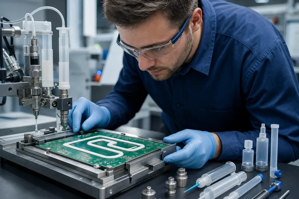
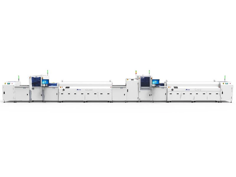
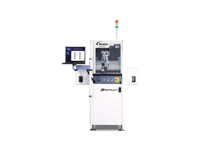
A coating machine can produce a clean-looking sample board while the production line around it creates rejects. The common scene is familiar: boards queue at the coater because the loader cannot keep pace, an operator turns panels by hand and loses orientation, or a UV inspection station finds exposed keep-out areas after the boards have already entered the oven. The equipment may all work. The line does not.
The shortest useful answer is this: plan the line as a sequence of validated handoffs. Start with the board and coating material, define orientation and inspection requirements, then choose loading, transfer, coating, curing, and unloading modules that preserve those decisions. A Complete Coating Line Solution should be specified as one process, not purchased as a coating machine plus a collection of conveyors.
A workable coating line starts with validated handoffs, not a list of machines
Every transfer changes risk. A board can be scratched, misoriented, contaminated, delayed outside its permitted process window, or sent to the wrong downstream route. That is why an automated conformal coating line needs an agreed handoff definition at each point: who or what releases the board, how its identity and orientation are retained, what condition it must be in, and what happens when it is rejected.
- Document the incoming condition. State board type, acceptable cleanliness, component population, carrier use, and required traceability before loading.
- Draw the physical route. Include loading, coating, UV inspection, cure, any board flip, final inspection, and unloading. Mark buffer positions and operator access, not just machine footprints.
- Set orientation rules. Identify the datum that defines top, bottom, leading edge, and program direction. Confirm that each conveyor and lift maintains it.
- Assign each quality check to a point in the route. A defect found before curing may be recoverable; the same defect found after final unload is usually a containment event.
- Run representative boards through the proposed sequence. Include the most densely populated board, the board with the tightest keep-out pattern, and the board that needs underside processing.
This approach also makes supplier discussions more useful. Instead of asking for “a complete line,” you can review a proposed coating line configuration against real boards, material data, takt expectations, and factory constraints.
Define the board, material, and cure constraints before selecting line modules
Line planning begins upstream of the dispenser. Collect the approved assembly drawings, coating keep-out data, material technical data, cure requirements, and the actual board mix. Do not rely on a single idealized panel. Variations in connector height, shielding, heat sinks, underside components, and depanelization condition can decide whether an otherwise sensible PCB coating line layout will run reliably.
Map coating access, keep-out areas, board orientation, and underside processing needs
Translate the coating drawing into machine-relevant decisions. Which areas require selective application? Are there connector openings, test pads, LEDs, switches, or grounding points that must remain free of material? Can the applicator access intended surfaces without collision risk? A keep-out zone that looks generous in CAD may be narrow once component tolerances, board position, and coating edge control are considered.
Underside coating is a separate routing decision, not a footnote. If boards must be processed on both sides, determine whether the process calls for an automatic board flipper, a controlled manual operation, or separate handling. The chosen method must protect uncured material and preserve the program reference. A flipped board that returns to the coater in the wrong orientation creates a defect pattern that can look random until someone traces it back to handling.
Match coating material behavior to the intended curing method and process sequence
Ask the material supplier what the coating needs before and during cure: required preparation, allowable time after application, cure method, ventilation needs, and sensitivity to thickness or shadowed regions. UV-cure materials, for example, still need a defined plan for areas light cannot reach if the material system has a secondary cure mechanism. Thermal and infrared curing introduce different questions about component heat exposure, board support, and dwell consistency.
CHUANGKAIDA configurations can include UV furnaces or infrared furnaces alongside coating and inspection equipment. The correct oven is determined by the approved material process and the assembly’s thermal limits, not by which cure module is easiest to fit into the available space.
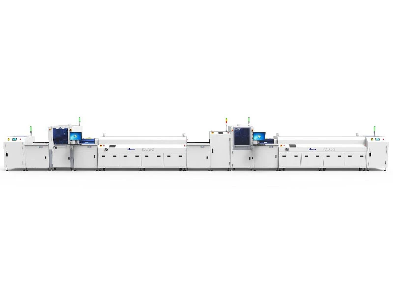
Design board handling around changeovers, floor layout, and operator involvement
Handling is where a line either earns its throughput or quietly gives it away. Start with board size range, support requirements, transfer direction, clearance around tall components, and the production mix. Then look at changeovers. If the plant runs frequent small lots, a highly automated route with long setup and recovery steps may be less useful than a simpler line with clear manual touchpoints.
Choose between manual loading, automatic lifts, conveyors, and board flipping
Manual loading and unloading suit lower volume, frequent product changes, or lines where an operator must make a visual judgment before release. They also demand defined work instructions: which side faces up, how boards are supported, where they may be touched, and how rejects are segregated.
Automatic lifts make sense where boards arrive or leave at a different elevation, where magazine-style flow is required, or where operators should not handle wet boards. Conveyors connect stations, but they must be evaluated for board support and for the time boards spend waiting between coating and cure. An automatic flipper belongs in the plan only when both-side processing is real and repeatable; adding one “just in case” consumes space and adds another orientation handoff to validate.
Leave room around every module for cleaning, maintenance, material replenishment, and recovery from a stopped board. The tightest floor plan is often the least serviceable one.
Place UV inspection and curing where they can contain defects before final unloading
A selective coating line with UV inspection is most useful when the inspection result can change what happens next. Put UV inspection after application and before final cure or final release when that sequence permits defects to be contained promptly. It gives operators a chance to identify missed coverage, coating in visible keep-out areas, poor edge definition, and obvious application inconsistency before boards disappear into downstream flow.
Define what UV inspection can verify and what still requires process validation
UV inspection is not a blanket proof of conformal coating quality. Its usefulness depends on the coating’s fluorescent response, lighting conditions, inspection method, board presentation, and acceptance criteria. It can make certain coverage and placement issues visible. It does not by itself prove film thickness, cure completion, adhesion, chemical resistance, or coverage in a shadowed area.
Build a layered control plan. Use the UV station for defined visual criteria, maintain the coating program and material controls that prevent errors, and validate the broader coating process with the methods required by your product and customer requirements. If an inspection station only produces ambiguous “looks good” decisions, it will become a bottleneck rather than a control point.
Turn a proposed CHUANGKAIDA coating line into a documented acceptance plan
CHUANGKAIDA describes line configurations that can combine manual board loading or unloading, automatic lifts, conveyors, iCoat3 or iCoat5 coating equipment, UV inspection stations, curing ovens, and an automatic board flipper. That flexibility is valuable only if the proposal is tied to written acceptance conditions.
For a CHUANGKAIDA complete coating line, ask for a line layout, module-by-module scope, utility assumptions, board handling sequence, interfaces, safety responsibilities, installation activities, commissioning scope, training, maintenance requirements, and spare-parts recommendations. Then attach sample boards and a test plan. Acceptance should cover the board types you actually build, stated orientation through every handoff, intended coating patterns, inspection routing, cure routing, alarms, and recovery after a stopped or rejected board.
Customization does not remove the need for this document. It makes the document more necessary.
Use a pre-purchase checklist to prevent line integration and commissioning delays
- Have you supplied representative bare and assembled boards, including difficult geometries and underside cases?
- Is the approved coating material and curing route defined, including any restrictions from the material supplier?
- Are coating areas, keep-outs, and inspection criteria available in controlled drawings or files?
- Can every station maintain board orientation, support the assembly properly, and handle the expected product range?
- Does the layout show operator positions, buffer needs, service clearance, material access, and reject handling?
- Is UV inspection assigned a specific acceptance role rather than a vague final check?
- Have you agreed on factory and site acceptance activities, installation support, commissioning responsibilities, maintenance, and spare parts?
Bring that checklist, your board set, and the material process data to the first line-layout review. That is the point to resolve the hard questions with a custom conformal coating line supplier—before equipment arrives, floor space is committed, and a missed handoff becomes an expensive commissioning delay.